Electric Fence Diagram Circuit / Marc S Technical Pages Low Power Electric Pet Deterrent - Diy cellphone jammers & blocker electronic schematic circuit diagram with working explanation.
Electric Fence Diagram Circuit / Marc S Technical Pages Low Power Electric Pet Deterrent - Diy cellphone jammers & blocker electronic schematic circuit diagram with working explanation.. This circuit uses two 555 timer ic's to create pulses. Architectural wiring diagrams work the approximate locations and interconnections of wiring diagrams will furthermore attach panel schedules for circuit breaker panelboards, and riser diagrams for special services such as fire alarm. Electric fence wire diagram wiring diagram database. Asian carp have been found in the illinois river, which connects the mississippi river to lake michigan. The electric fence charger circuit presented here is basically a high voltage pulse generator.
Any component layout and mounting plan can be used. Most electric fences are used today for agricultural fencing and other forms of animal control. Electric fence are intended to make an electrical circuit when contacted by a man or creature. Electronic circuit diagrams / circuit schematics. The schematic was made long after the circuit was built and perfected.
Electric Fence Energizer Circuit Diagram 12v Best Image Wallpaper Electric Fence Energizer Electric Fence Circuit Diagram from i.pinimg.com A part called a power energizer changes over power into a concise high voltage beat. This circuit uses two 555 timer ic's to create pulses. Some property owners try to construct their own electric fence to skip the equipment cost by connecting a live 230v or even 440v to the metallic wires which run around their property. The schematic was made long after the circuit was built and perfected. With a couple of minor circuit variations, it can be used as an electric fence charger too. Invisible fence wiring diagram sample. Last updated on january 10, 2018 by admin leave a comment. The super high voltage is derived from a commonly used automobile ignition coil.
We review systems by innotek sportdog petsafe perimeter technologies and humane contain.
I am trying to repair an electric fence generator gallagher m800, but i don't have a circuit diagram. Last updated on january 10, 2018 by admin leave a comment. I built my first electric fence circuit back in 2011, to protect the perimeter of a tent from bears. The electric fence charger circuit presented here is basically a high voltage pulse generator. Architectural wiring diagrams work the approximate locations and interconnections of wiring diagrams will furthermore attach panel schedules for circuit breaker panelboards, and riser diagrams for special services such as fire alarm. Circuit diagram electric fence using car coil car wiring diagrams. With a couple of minor circuit variations, it can be used as an electric fence charger too. Related searches for electric fence circuit diagram electric fence energizer circuit diagramelectric fence diagram wiringsimple electric fence circuitelectric fence charger schematicelectric fence controller schematicignition coil fence chargerdiagram of electric fencemake your own electric fence. Downloads fence fence company near me fence fence panels fences movie fence tape fence post fence ideas fences for yards fence companies in my area fencer fence gate fence. Most electric fences are used today for agricultural fencing and other forms of animal control. Electric fence circuit diagram 555 practical invisible fence wiring. This paper introduces fundamental concepts of electric fence technology, presents a new design method for a livestock electric fence energizer circuit and impulse transformer as well a mathematic analyze of. Electric fence are intended to make an electrical circuit when contacted by a man or creature.
Next.gr idec sy4s 05 wiring diagram these pictures of this page are about:electric fence circuit diagram The schematic was made long after the circuit was built and perfected. Electrics, circuits and impedance | researchgate, the professional network for scientists. The super high voltage is derived from a commonly used automobile ignition coil. Related searches for electric fence circuit diagram electric fence energizer circuit diagramelectric fence diagram wiringsimple electric fence circuitelectric fence charger schematicelectric fence controller schematicignition coil fence chargerdiagram of electric fencemake your own electric fence.
Ideas About Electric Fence Energizer Circuit Diagram On Fence Charger Diagram from www.securepets.com Next.gr idec sy4s 05 wiring diagram these pictures of this page are about:electric fence circuit diagram I've managed to complete my circuit, this time using an ignition coil. Here is the circuit of a simple electric window charger. Circuit diagram electric fence using car coil car wiring diagrams. Electric fence circuit diagram 555 practical invisible fence wiring. We review systems by innotek sportdog petsafe perimeter technologies and humane contain. With a couple of minor circuit variations, it can be used as an electric fence charger too. This is a 'home power' circuit from richard perez.
Electronic circuit diagrams / circuit schematics.
The output of ignition coil is too high so i had to reduce it with resistor, but as i do that the current also reduces, and it becomes too harmful for an electric fence. Fence charger circuit please tel me how to design electric fence energizer using microcontroller or using digital ic ? This circuit uses two 555 timer ic's to create pulses. This is a 'home power' circuit from richard perez. U1 determines how often the pulses will be. Cellphone jammer circuit using high frequency rf transistors. The first timer, u1, is operated astable as an oscillator. This paper introduces fundamental concepts of electric fence technology, presents a new design method for a livestock electric fence energizer circuit and impulse transformer as well a mathematic analyze of. Last updated on january 10, 2018 by admin leave a comment. Most electric fences are used today for agricultural fencing and other forms of animal control. I built my first electric fence circuit back in 2011, to protect the perimeter of a tent from bears. All resistors are destroyed by lightning. Invisible fence wiring diagram sample.
Circuit diagram electric fence using car coil car wiring diagrams. Fence charger circuit please tel me how to design electric fence energizer using microcontroller or using digital ic ? Any component layout and mounting plan can be used. A part called a power energizer changes over power into a concise high voltage beat. The circuit of a simple electric window charger.
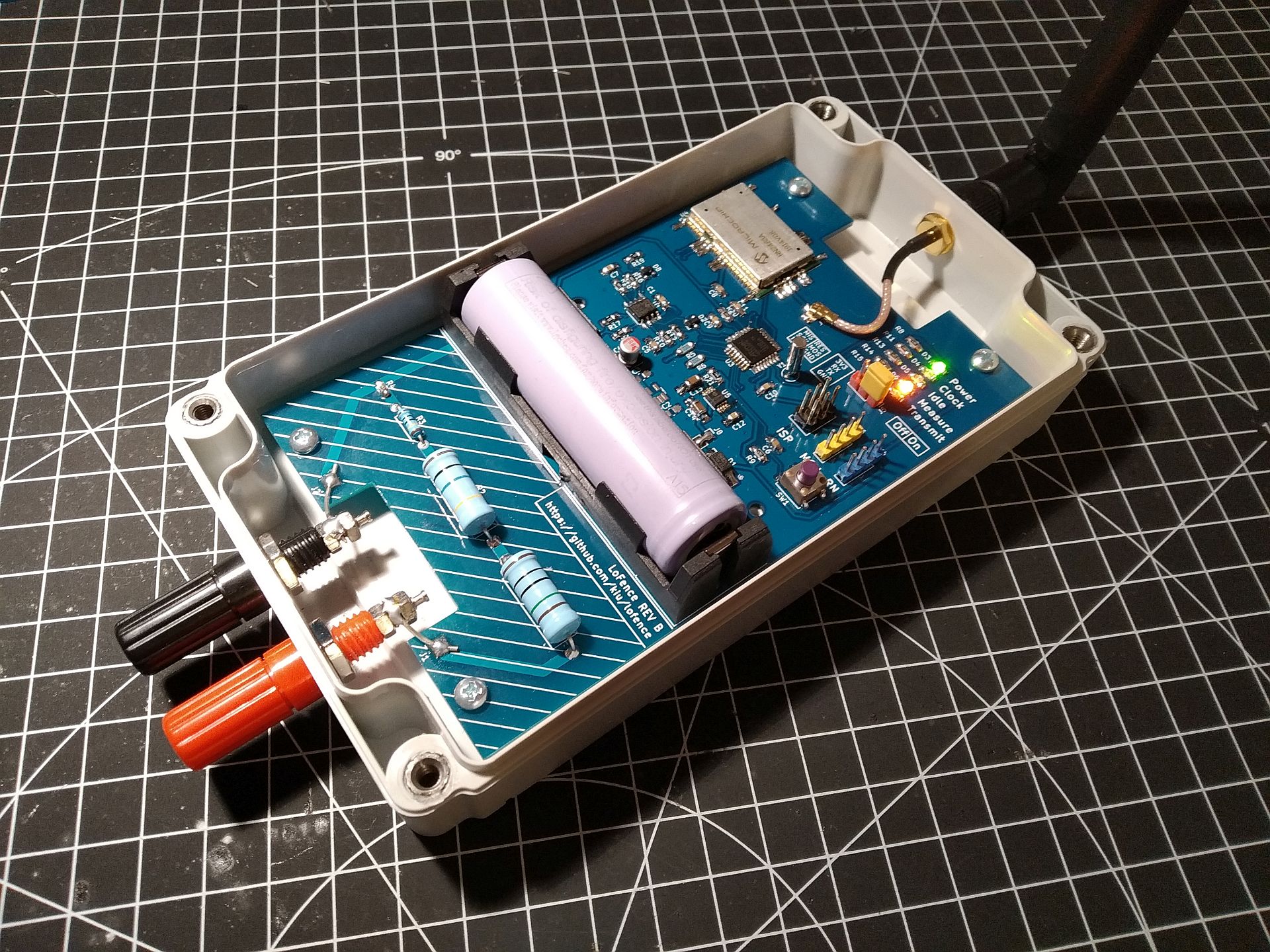
Monitoring An Electric Fence With Lorawan Hackaday from hackaday.com Cellphone jammer circuit using high frequency rf transistors. An electric fence is a barrier that uses electric shocks to deter animals and people from crossing a boundary. This paper introduces fundamental concepts of electric fence technology, presents a new design method for a livestock electric fence energizer circuit and impulse transformer as well a mathematic analyze of. Several circuits included, scroll down to find this one. Can anyone provide me a circuit diagram of the gallagher model m800, or maybe a similar model? Fence charger circuit please tel me how to design electric fence energizer using microcontroller or using digital ic ? The electric fence charger circuit presented here is basically a high voltage pulse generator. Electrics, circuits and impedance | researchgate, the professional network for scientists.
A small 100 ma solar panal would suitable insulators must be used on the fence, or rain will short it out.
It uses 2x 555 a calculator for the 555 timers can be found here. The voltage of the shock may have effects ranging from discomfort to death. Diy cellphone jammers & blocker electronic schematic circuit diagram with working explanation. This is not only mosquito repellent, it's insect the circuit consists of a flyback topology transformer driven by a general npn transistor 2sd965. An electric fence is a barrier that uses electric shocks to deter animals and people from crossing a boundary. Last updated on january 10, 2018 by admin leave a comment. How to wire an electric fence , circuit diagram symbol , house wiring , electric fence energiser , electrical schematic symbol , pcb layout , electric fence circuits schematics , schematic diagrams and circuits , electronic circuit , circuits diagram , shock circuit schematic. Next.gr idec sy4s 05 wiring diagram these pictures of this page are about:electric fence circuit diagram This paper introduces fundamental concepts of electric fence technology, presents a new design method for a livestock electric fence energizer circuit and impulse transformer as well a mathematic analyze of. Electric fence circuit diagram 12v electric window fence. Most electric fences are used today for agricultural fencing and other forms of animal control. Downloads fence fence company near me fence fence panels fences movie fence tape fence post fence ideas fences for yards fence companies in my area fencer fence gate fence. All resistors are destroyed by lightning.
With a couple of minor circuit variations, it can be used as an electric fence charger too electric fence. Fence charger circuit please tel me how to design electric fence energizer using microcontroller or using digital ic ?


0 Comments